This post will cover the lines that run from the bulkhead fitting on the inner fender well to the engine.
Heater Hoses - Here you can see the stainless o-ring to MPT fittings in the water pump. I removed the pressed in nipples and used a pipe tap to thread the holes for the fittings. I began at the pump with a 90 degree fitting.
And another 90 at the bulkhead connector.
2nd heater hose.
Next up were the A/C lines. In the last post I mentioned that I wasn't going to be able to use the "standard" service port fittings due to a clearance issue. I sourced a set of weld-on service ports from Roy at Vintage Air. I played around with either locating them as shown here.
Or, as shown here.
I decided to located them this way, thinking it was a cleaner look than the first choice.
New ports welded in place.
And after cleaning them up and re-finishing.
Attaching the line.
High side line complete.
Low side complete.
Next up will be the lines to the evaporator and heater core inside of the firewall.
This is the first days work on fabricating the HVAC lines. I am using the Vintage Air "Clip Sleeve" lines (an Aeroquip product, I have to plug them since I work for Eaton, which is the mother company). In the past, A/C lines have always been a b*%tch. I don't like the look of what comes with most "kits" since I like to try and conceal them as much as possible. The stuff you get crimped at your local parts house is ok but not too attractive and I never seem to get the one guy that is the "pro" to do my lines. With this set up, it is unbelievably easy to make up your own lines. That doesn't mean it is cheap. But in the end it is worth the added expense. I also used this for the heater lines. They will outlast the car!
This is a finished end. There is the fitting, a "cage" and two special clamps. More on the assembly in a minute...
I used these two metal straps to hold the lines up during assembly. These will be fabricated to make a clip to hold the lines after I get the lines all laid out. The white ty-wraps are just my extra set of hands. They will be swapped for nice black ones when I am sure everything is where I want it.
This is at the front, inside of the passenger side fender well (remember there is a bulkhead connector here). The two lines hanging down to the right will go to the condenser.
Here you can see where I mounted the drier on the outside edge of the firewall.
Fitting assembly - First cut the line to length. I used my handy dandy Craftsman cutting tool, worked great!
The two special clamps and the cage.
Double check the length and get a rough idea of the orientation (clocking of the fitting).
Lube the two o-rings. I used Vintage Air o-ring lube. You can use refrigerant oil as well.
Slide the clamps on the line.
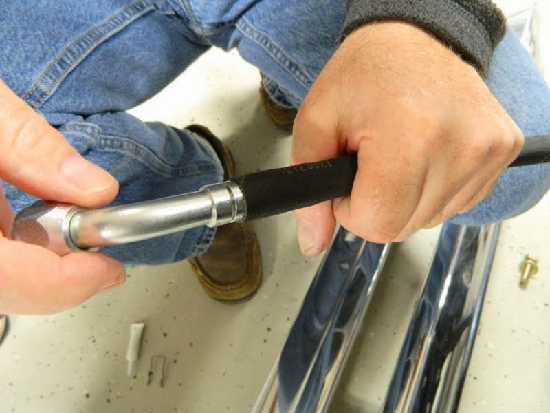
Insert the fitting. All that is needed is hand strength.
The cage clips in the groove on the fitting.
Now is the time to clock the fitting however it needs to be. Once you squeeze the clamps it won't turn and the line doesn't twist much.
Slide the clamps up into place on the two grooves on the cage. The purpose of the cage is to properly locate each clamp over the o-ring on the fitting.
Use the Clip Sleeve tool to lock the clamps in place.
Finished condenser lines.
I notched the bumper bracket so the condenser lines would not be in a bind. I will go back and weld on a new flange before I mount the bumper for the final time.
Drier lines.
The extra hole in the firewall next to the bulkhead connector is where the wires for the binary switch and the heater control valve will pass through.
Finished hose mounting clips.
Here you can see the heater control valve.
Uh Oh...... This is one of the service port fittings. Not going to be enough clearance to the fender well to allow servicing. Two options for this. Either I will use this fitting on the inside of the fender well at the bulkhead connector or I will use in-line service port fittings.
I will figure that out in the morning!!