This post covers the fuel line fabrication. I used 3/8" stainless steel with AN fittings. I sourced the tubing from Inline Tube. They were very helpful and pleasant to deal with. The fuel line will be two sections, one front and one rear with a union connecting them together.
This pic is the engine compartment showing the Aeroquip -6 Push Loc line routed from the passenger side fuel rail to a 90 degree bulkhead fitting at the rear of the inner fender.

From there the first line will run along the subframe connector towards the rear. First bend.


At the front the hard line will have a flex line to the bulkhead fitting.

Needed a slight offset to follow the contour of the subframe.
From here the line runs rearward along the subframe and will have a union just ahead of the lower rear control arm mount. From there it will connect to the rear section.

This is the beginning of the rear section. I started this one at the tank and worked toward the front to meet the end of the front section. I was really happy that I got this right on the first try! It is a pretty complex run and fit perfectly.

Next bends. My method, I used some old solid copper wire to make templates before forming the actual lines. I would adjust the template to match the actual line after each bend and then re-check the template to the car for any further adjustments.

Connection to the fuel tank.
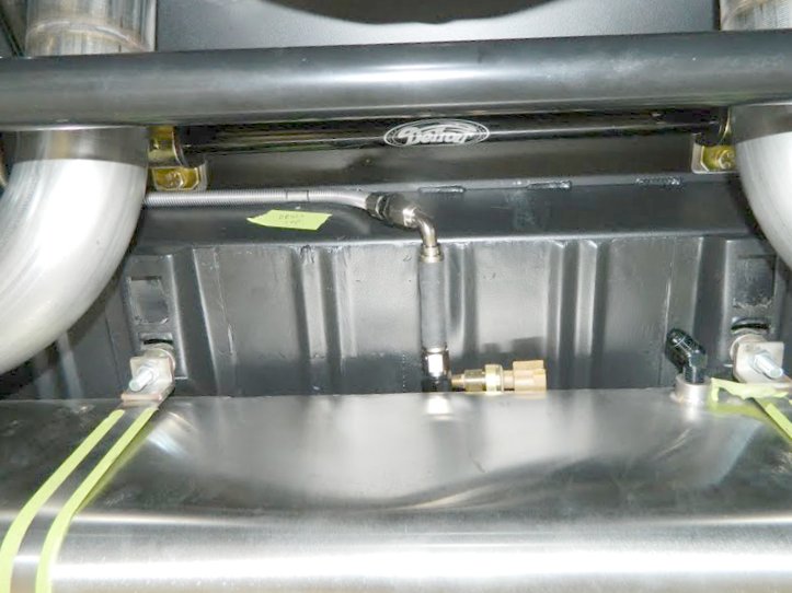
Coming from the tank (right side of the picture).

Moving forward from the tank along the inside of the frame rail. Some small wood workers bar clamps make a nice second pair of hands!

This is where the front and rear lines will be joined by a union. I waited to offset the front line until this point so I would know exactly where the rear line would be.

Offsetting the front line.

Here I am installing the spring wrap before putting the last fitting on the front line. The piece of green tape in the last picture was my reminder, sucks if you forget to install the wrap before the last fitting!

Front line with spring wrap and clamps in place.

Completed union between front and rear sections.

In this pic the rear line has the spring wrap and clamps in place.

Rear line looking rearward from the union.

Front line looking forward from the union.


Front connection to the flex line and bulkhead fitting.

One more shot of the lines.