This post will cover the wiring forward of the firewall for the heater control valve and the binary switch.
I ran the heater control valve wires with the hoses to the front where the valve is located.
Connects to the valve with insulated spade connectors.
These are the pressure switch leads.
Also connected with insulated spade connectors.
These are the hard lines I had made by Vintage Air that go from the heater core to the bulkhead connector on the firewall. The top line of each pair is the actual line. The line shown below each finished line is the template I made up from leftover fittings. I sent these templates to Vintage Air. As you can see, the finished lines match perfectly.
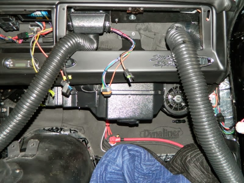
This is a shot of the body wiring connections to the evaporator assembly. The red and white leads to the left are the blower motor power feed. The connector to the right contains battery feed (control circuit), ignition feed, ground & compressor clutch feed.
This connector feeds the heater control valve and the binary switch.
This is the engine side of the firewall where the control wires exit the cabin.
I mounted the Dakota Digital HVAC control box to the front evaporator mounting bracket. My goal was to mount all of the controls to the evaporator assembly so that installing or removing it (hoping that never happens!) is a matter of just unplugging the connectors and disconnecting the lines.
High and low pressure lines installed.
A few more shots of the evaporator before installing.
Here we go, one more time!
Odd shot here. This is looking up at the hoses and lines in place.
The fitting at the bottom will be the drain.