Time for the battery cables. I used #1 Hy-flex battery/welding cable. The main run will be between the bulkhead connectors at the front to the battery, disconnect switch and main fuse in the trunk.
Began by crimping the terminals to the cables. This end will be at the front (bulk head connectors).
Pulled the other end through to the trunk.
The cables run to the trunk along the pinch weld on the passenger side door jamb. I will fab up some sheet metal covers later for along the door jamb. There will be a false floor at the front foot well area. The carpet will make all of this disappear.
The smaller hole to the right is for the starter solenoid lead. Waiting on the small bulkhead connector parts to arrive.
This is a body ground stud which is located just behind the rear seat bulk head in the trunk. The small wire is the fuel pump ground.
These are the battery terminals, I chose them because I like the fact that the cables can attach with ring terminals.
This is the negative terminal with the 8 ga. body ground lead.
This is the crimper I used on the battery terminals. A bit of an old school tool borrowed from work.
In this shot you can see the positive cable routed up the rear bulk head to the main fuse mounted on the bottom of the package tray.
Then from the line side of the main fuse to the disconnect switch and then down to the battery.
At this point I moved the car back over to the lift. Pushed her outside to move her over and couldn't resist posting a few pics of what she looks like so far.
Here are the details on the glove box switch panel:
The panel will house momentary push buttons for the Phantom ignition (1) and the Dakota VHX instrument cluster (2). And for the cooling fan controller a temp adjustment potentiometer and indicating LED.
I also mounted the OBDII connector in the glove box.
A side note - this is the pile of wire left over from basically rebuilding the various harnesses. If the harnesses had been installed as received, most all of this wire would have been stuffed in somewhere. I wanted more of a purpose built harness specifically for this project where everything is incorporated rather than scabbed together. It took me about 3 weeks of evenings and weekends but it came out really nice.
Problem:
Although the molded plastic glove box insert that came with the Vintage Air Sure Fit kit is a nice part, it had a few short comings for this project. It had to be installed from the rear which presented an issue installing the evaporator and ducts.
Solution:
Fabricate a new sheet metal insert to install from the front after the evaporator and ducts are installed.
I started with a poster board mock up.
The mock up piece next to the plastic V/A version.
Transferring to 20 ga. sheet metal.
Cut and marked to bend.
Forming up in the new brake I bought from Harbor Freight. With the coupon it was only $179, should have bought this long ago!
I cut the ends from some 16 ga. for stiffness.
Tacked the ends in place.
New vs. the plastic part.
Installs from the front. The sides tuck in behind the dash face.
Marking the location for the Aux. power port and the UBS port for the sound system.
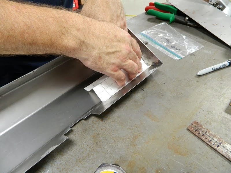
This template is for a switch mounting panel.
Switch panel completed.
Hole punched for the Aux power receptacle.
The large cut out is for the connections to the switch panel.
This is the USB receptacle for the audio system.
Details on the switch panel in the next entry.