Here is where I mounted the horns (one on each side) I wanted them out of sight. All I had to do was to enlarge the mounting hole on the horn bracket to 7/16".
Lining up the fenders.
Grille valance is next.
During mock up I had the DCC cooling fan controller on a temporary bracket behind the grille. I needed to have everything up front in place to determine the exact mounting location.
Decided on this location. It is hidden behind the headlight bucket and the bumper. I can easily get to the adjustment pot by reaching up behind the bumper. The unit is weather tight.
Picked up a new grille as the one that came with the car was a bit flattened out at the peak in the middle.
Adding the embellishment :)
I will be blacking out the front of the air filter.
Headlight buckets are next.
These are the DSE Bright Driver headlights. Very well made H4 conversions.
Driver's side trim.
Quick headlight test.
Passenger side trim.
A few shots of the ducting installed. I mocked this up earlier so it was just a matter of putting them back in. You sure find out how little space these cars have behind the dash!!
The control panel with power applied.
This thing is so cool!
This post will cover the wiring forward of the firewall for the heater control valve and the binary switch.
I ran the heater control valve wires with the hoses to the front where the valve is located.
Connects to the valve with insulated spade connectors.
These are the pressure switch leads.
Also connected with insulated spade connectors.
These are the hard lines I had made by Vintage Air that go from the heater core to the bulkhead connector on the firewall. The top line of each pair is the actual line. The line shown below each finished line is the template I made up from leftover fittings. I sent these templates to Vintage Air. As you can see, the finished lines match perfectly.
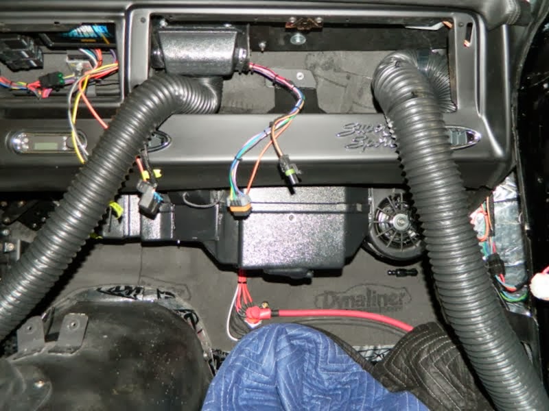
This is a shot of the body wiring connections to the evaporator assembly. The red and white leads to the left are the blower motor power feed. The connector to the right contains battery feed (control circuit), ignition feed, ground & compressor clutch feed.
This connector feeds the heater control valve and the binary switch.
This is the engine side of the firewall where the control wires exit the cabin.
I mounted the Dakota Digital HVAC control box to the front evaporator mounting bracket. My goal was to mount all of the controls to the evaporator assembly so that installing or removing it (hoping that never happens!) is a matter of just unplugging the connectors and disconnecting the lines.
High and low pressure lines installed.
A few more shots of the evaporator before installing.
Here we go, one more time!
Odd shot here. This is looking up at the hoses and lines in place.
The fitting at the bottom will be the drain.
This post will cover the lines that run from the bulkhead fitting on the inner fender well to the engine.
Heater Hoses - Here you can see the stainless o-ring to MPT fittings in the water pump. I removed the pressed in nipples and used a pipe tap to thread the holes for the fittings. I began at the pump with a 90 degree fitting.
And another 90 at the bulkhead connector.
2nd heater hose.
Next up were the A/C lines. In the last post I mentioned that I wasn't going to be able to use the "standard" service port fittings due to a clearance issue. I sourced a set of weld-on service ports from Roy at Vintage Air. I played around with either locating them as shown here.
Or, as shown here.
I decided to located them this way, thinking it was a cleaner look than the first choice.
New ports welded in place.
And after cleaning them up and re-finishing.
Attaching the line.
High side line complete.
Low side complete.
Next up will be the lines to the evaporator and heater core inside of the firewall.