Finishing up pretty much the last of the under dash terminations.
Steering column connector and the retained accessory power relays
Driver's side kick panel. You can see the connectors for the power windows, rear lighting harness & power door locks.
Tying up the run across to the passenger side. This includes courtesy light connections and various items that will be located in the glove box.
Radio harness coming together.
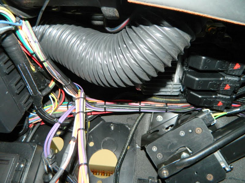
The coiled leads are the a/c clutch leads, the others are various power and ground leads which will go the the battery bulkhead connectors.
This entry covers the installation of the harness for the Nu-Relics power windows. I made a few mods to the harness. It was great as it came but I wanted to integrate it a bit into the chassis harness. The mods were just two. #1 was to sleeve the harness with heat shrink in any area that needed protection, like under the door sill plate and the run across the back set area. #2 was to add a couple of connectors at the driver's kick panel for connection to the door and the chassis harness.
First up was removing the wires for the connectors.
A bit of mock up to determine where the heat shrink was needed.
Also removed the tape wrap.
Applying the heat shrink
Punching the hole in the cowl for the boot
Corresponding hole in the door
Adding the weatherpack connectors at the driver's kick panel
Routed to the driver's door
This will cover the front lighting and cooling fan wiring harness fabrication.
This is the OEM style bulkhead connector which was relocated further outboard to get it out of the engine compartment. The right half of the connector is pretty much as American Autowire planned with exception of removing any unused leads. This will be only lighting and the horn lead.
Tying up with tape to keep everything straight and tangle free.
One horn will be mounted on each side near the front tucked up in the fender wells.
Similar to how I did the fuel pump leads, this will be encased in heat shrink for protection from the elements.
The inboard half of the OEM style bulkhead connector will be re-purposed for the cooling fans. First I removed all of the original leads which were intended for the engine connections. Then began recreating with the leads needed for the Delta Current Control PWM fan controller.
The one somewhat tricky item was accommodating the 8 ga. power and ground leads using the OEM style connector. I accomplished this by paralleling 2 10 ga. leads through the connector then connecting them to the 8 ga. leads. The controller requires 3 other leads as well.
This is the DCC PWM fan controller. I mounted it off of the grille/driver's side headlight support. Out of sight, close to the radiator and accessible if needed.
Lighting and cooling fan harnesses
At this point, with the engine harness complete and needing to begin the front end lighting and cooling fan harnesses, it is time to install the inner fenders and core support. Pretty straight forward since all of this was fitted during mock up.
Driver's side inner fender
Passenger side inner fender well
Core support set in place
Installing hardware (all stainless steel)
Pardon the dust! These have been sitting around for a while!!